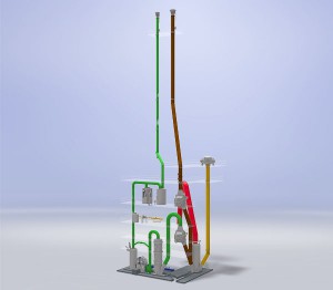
Stack Systems (Clean Gas Stack A17 including Demister F17, Bypass Valve K17, Ignition System X17 and Flame Monitoring System / Emergency Stack A12 including Control Valve K12, Ignition System X12 and Flame Monitoring System)
 From the overflow valve the clean process gas is routed to the clean gas stack A17 via the demister F17, where residual water droplets are precipitated from the gas stream. At the stack head the process gas is ignited and continuously combusted whilst being released to atmosphere.
Emergency Stack for Safe Operation
During start-up and shutdown of the furnace as well as during emergency situations the furnace off-gas is emitted via the emergency stack A12. Again, the CO-rich gas is ignited and combusted at the stack head.
Functionality of the Ignition System
The ignition systems X17/X12 are designed as the so-called “climbing flame”. The ignition gas, usually natural gas, is ignited in the ignition control box with two high-voltage electrodes. Ignition gas as well as combustion air is added at several points in the flame pipe rising up to the stack head, allowing the ignition flame in the pipe to rise from bottom to top and finally igniting the process gas escaping at the stack head. Ignition as well as the presence of the flame is monitored by the flame monitoring system using thermocouples or infra-red sensors.


