Non-Return Valve B18
 The non-return valve B18 creates a gas-tight water seal and separates the gas cleaning system from the consumer network. The geometry of the vessel prevents the return flow of gas form the consumer network into the gas cleaning plant up to a predetermined back pressure.
Controlled Distribution of the Clean Gas
The conditioned gas exiting the gas cleaning plant is distributed to the consumer network (gas export) and/or the clean gas stack (flare) in a controlled manner using the overflow and non-return valves. These separated gas flows are defined by
- the relevant water levels in the overflow-valve and the non-return valve
- the excess clean gas pressure generated by the Disintegrator
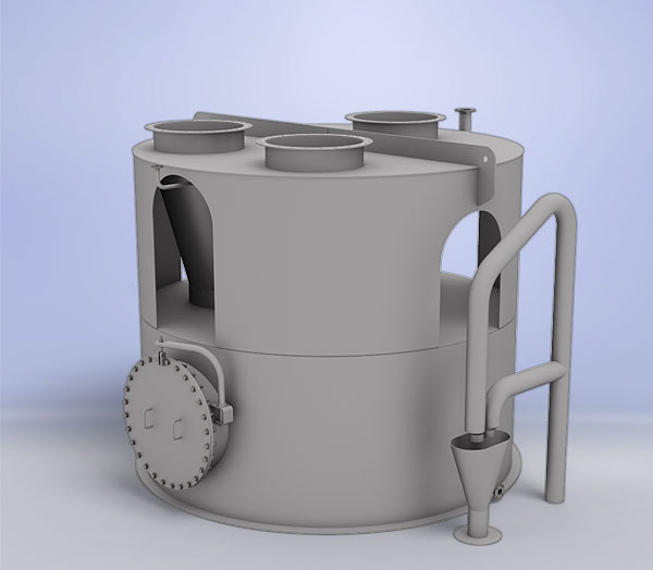
Working Principle of the Non-Return Valve
The non-return valve vessel is partially filled with water; the water level is adjustable to two predefined levels by the integrated water level control system. The clean gas inlet pipe is always immersed in water, even at the lowest water level. This allows for gas export but blocked gas return. At the higher water level, even the maximum excess pressure generated by the disintegrator cannot overcome the water head, thus preventing gas flow to the consumer network.
If the immersion depth in the overflow valve B17 is smaller than the one in the non-return valve B18, then the clean gas flows towards the clean gas stack. Vice versa, if the immersion depth in the overflow valve is higher than in the non-return valve, then the clean gas is routed to the consumer system via the non-return valve.
To ensure a constant water level in the vessel, “sealing water” is continuously supplied. The overflow leaves the vessel via the water level control system and is drained to the foundation sump.

