Functional Description of a typical THEISEN Gas-Cleaning Plant
 The purpose and task of the THEISEN Gas-Cleaning Plant is to extract the dust laden, hot CO gas from the smelter, to cool the off-gas in a safe manner in an oxygen free environment, to clean the gas according to contractual specifications to be suitable for atmospheric discharge and/or to condition the gas to be suitable as fuel source for calorific utilisation.
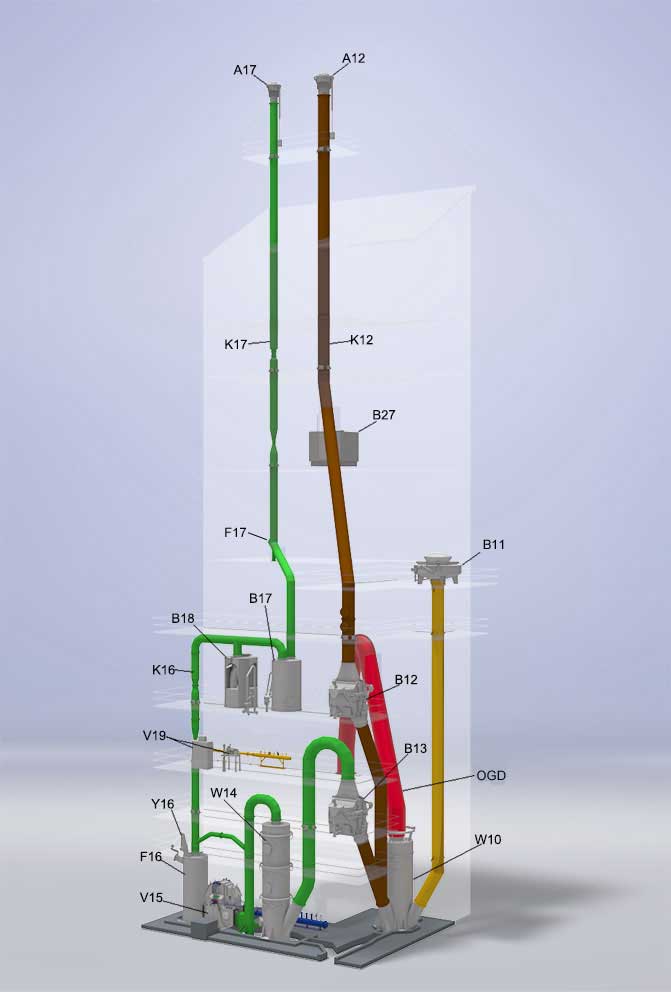
The crude gas generated in the smelter is extracted from the furnace and routed to the gas cleaning plant by the water cooled Furnace Off-Gas Duct (OGD). The OGD water cooling system comprises of several external cooling water channels providing cooling of the various pipe sections.
The furnace off-gas duct connects the smelting furnace with the Primary Quench Cooler W10 installed on the corresponding drain sump. The hot and dust-laden furnace gas in co-current operation is sprayed with water from numerous spray nozzles, cooling down the gas and scrubbing out coarse dust.
From the quench cooler a gas duct leads to the Safety Valve B11, which limits the maximum pressure in the gas system in case of a sudden and short-term pressure rise within the furnace, which cannot be compensated by the pressure control system incorporated in the gas cleaning plant.
During normal operation (clean gas mode) of the gas cleaning plant, the smelter off-gas flows via the primary quench cooler to the open Clean Gas Rotary Hood Water Seal B13 and further to the Cooling and Washing Tower W14, installed on the corresponding drain sump.
Here, in counter-current flow, the gas is sprayed with water for further pre-cleaning and cooling down the gas to the desired temperature for final cleaning in the THEISEN-Disintegrator V15.
The THEISEN Disintegrator is a highly effective rotary wet scrubber simultaneously acting as an ID fan. For final gas cleaning washing water is fed to the rotating machine and internally converted into a fine scrubbing mist, thus, providing a huge boundary surface between gas and liquid. Very high relative velocities between gas, liquid and particles are also produced and highest separating efficiency rates are consequently achieved. Additionally the disintegrator exhausts the furnace off-gas and drafts the process gas through all sections of the gas cleaning plant, compensating all plant internal pressure losses and supplying clean gas of required excess pressure to be utilized in downstream consumer systems.
Downstream of the disintegrator the associated Water Separator F16 is arranged, in which the wash water droplets, now having embedded the fine solids, are separated from the cleaned gas.
The Rupture Disk Safety Device Y16, installed at the top of the water separator, acts as an overpressure relief valve in the event of an impermissible increase in pressure within the clean gas section.
With the Control Valve K16, installed downstream the water separator, the furnace gas pressure is controlled.
Adjusting the two subsequent water seals Overflow Valve B17 and Non-Return Valve B18 the clean gas is routed in the desired ratios to the flare stack and/or the gas consumer system. The overflow valve also provides a flashback arrestor function between the flame head and the gas cleaning plant. Similarly the non-return valve blocks return gas flow from the consumer system back to the gas cleaning plant.
Excess clean gas not fed into a consumer system is routed to the Clean Gas Flare Stack System A17 to be emitted as combusted waste gas. Within the clean gas stack the Demister F17 is integrated to remove fine water droplets from the gas before gas ignition.
The Disintegrator is designed to compensate the plant internal pressure losses and to provide the requested gas pressure at the outlet of the non-return valve. Here, the water-saturated clean gas may be stored in a gas tank while further gas transport to the consumer is done by a booster device.
To monitor the clean gas flows to the consumer system and to the clean gas stack, two venturi-type gas flow measurements are installed; behind the water separator as well as behind the overflow valve.
In the event of failures in the gas cleaning plant or in the smelter, the raw gas will be routed to the Emergency Flare Stack System A12 and flared off (emergency stack mode). In this situation, the clean gas rotary hood water seal B13 will close before the Emergency Stack Rotary Hood Water Seal B12 will open.
Also within the emergency stack the Control Valve K12 is installed. By changing over the rotary hood water seals to emergency stack operation, the Furnace Pressure Control will also be switched over automatically from the clean gas valve K16 to the emergency stack valve K12.
Both operating modes (emergency stack mode – clean gas mode) are interlocked to ensure that no atmospheric air is able to enter the off-gas system.
In the event of a failure during the operation of the gas cleaning plant, which could lead to unsafe conditions, the system will automatically be switched to emergency stack mode (fail safe principle). The main components of this changeover, the two rotary hood water seals, are based on a well-proven design and constitute a major safety feature of the THEISEN gas cleaning plant!
The Clean Gas Analysis Installation X19 continuously monitors the CO, CO2, H2 and O2 content in the clean gas extracted from the process downstream the water separator F16. Hereby the gas cleaning system and all downstream arranged components are protected regarding explosive gas mixtures due to leakage and intake of oxygen. At the same time important information about the operation of the smelter and the gas cleaning plant is available.
Before smelting start the furnace as well as all sections of the gas cleaning plant must be inertised, i.e. purged with nitrogen to achieve an oxygen-free atmosphere. Also after shut-down and especially during emergency situations the gas cleaning plant is purged with inert gas to minimize explosion risks.
The Clean And Emergency Water Tank B27 acts as a reservoir to continuously provide clean sealing water as well as, in the event of disturbances of the process water supply or power outage, emergency cooling water. The tank is installed at a height so that all required consumers are gravity fed with clean water.

